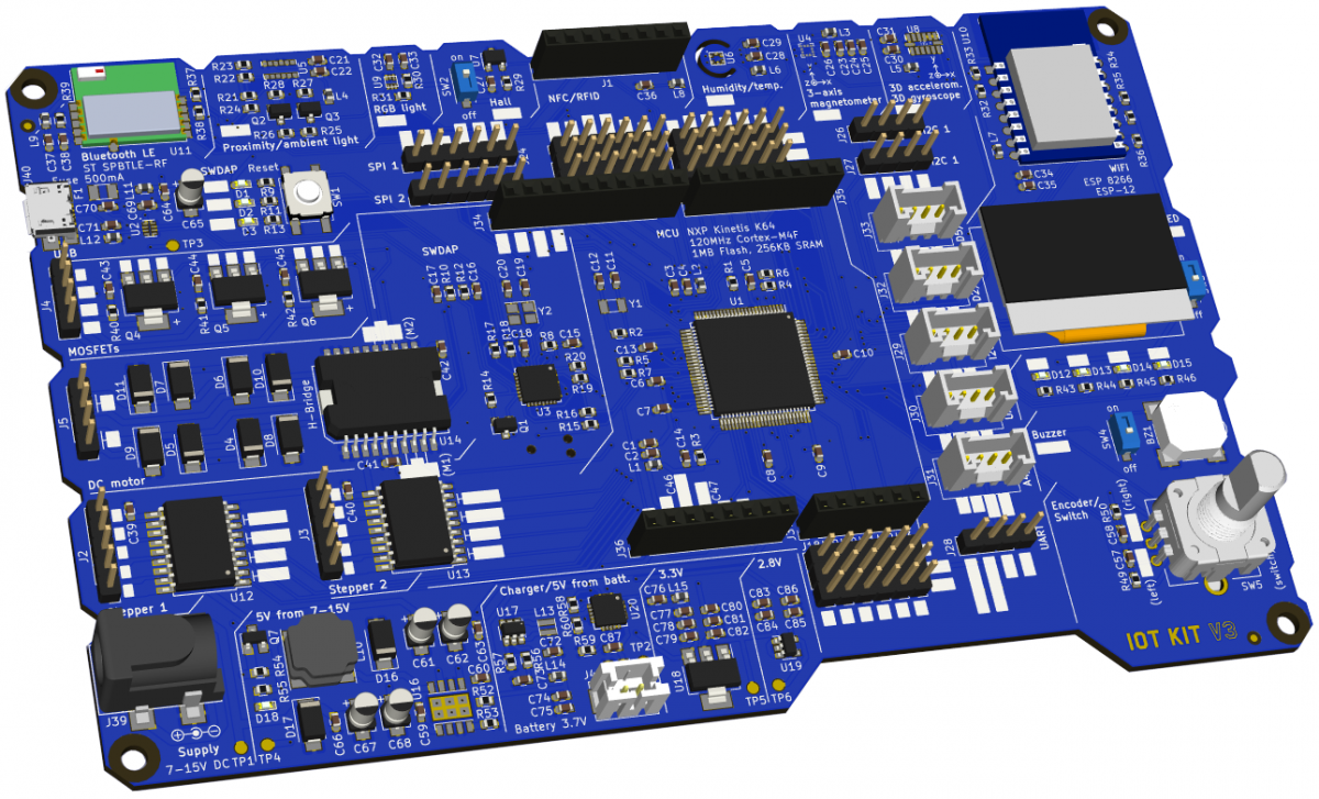
Board front, rendered in KiCad
IoT Kit V3 was designed primarily as a learning and experimentation platform for use in courses and workshops around the Internet of Things (IoT), but also for standalone low power applications. The board is based on the Freedom-K64F design by NXP / arm mbed. Like it, IoT Kit V3 features a powerful NXP Kinetis K64 MCU, and additionally various on-board sensors, drivers and an OLED display for a multitude of experiments and applications. IoT Kit V3 integrates all functionality in one board and thus supersedes V1 and V2 which were merely shields for Arduino Leonardo / Arch Pro boards.
Features
- NXP Kinetis K64 MCU
- ARM® Cortex®-M4F core running at 50 MHz
- 1 MB Flash memory
- 256 KB SRAM
- SPI (2)
- I2C (2)
- UART
- PWM
- USB (Micro B connector)
On-board peripherals and expansion
- 1 x rotary encoder / button
- OLED display (128x64 pixels)
- 4 x user LEDs
- buzzer
- WiFi module (Espressif ESP32 WROOM, ESP-12S)
- Bluetooth LE module (ST SPBTLE-RF)
- Proximity / ambient light sensor (ST VL6180X IR Time-of-Flight)
- RGB light sensor (Renesas/IntersiI SL29125)
- Hall-effect sensor (Allegro A1221ELHLT-T)
- Humidity / temperature sensor (ST HTS221)
- 3-axis magnetometer (ST LIS3MDL)
- 3D accelerometer/gyroscope (ST LSM6DSL)
- NFC/RFID interface
- 1 x DC motor driver (ST L298P)
- 2 x stepper motor driver (TI ULN2803A)
- 3 x MOSFET (DMN3032LE)
- 5 x Grove connectors
- Arduino Uno headers
Programming
IoT Kit V3 can be programmed as FRDM-K64F using the Arm Mbed Online Compiler (browser based) or offline toolchains.
Many code examples from Marcel Bernet's courses with IoT Kit are available on his GitHub account.
Design
IoT Kit V3 was designed using KiCad 4 and 5. (Actually, this project was my first KiCad design...) Design files will be available shortly on my GitHub account.
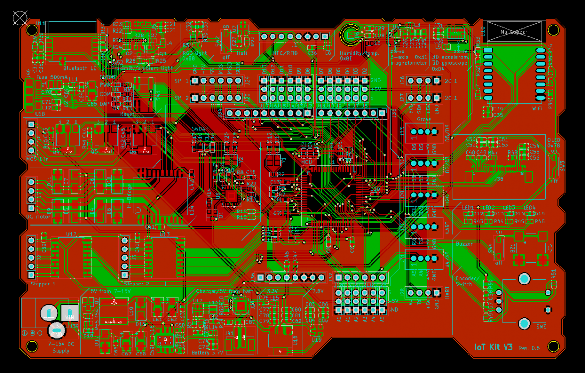
Screenshot of layout revision 0.6, May 2018
Bugs and fixes
As expected, the first revision had a bunch of hardware issues which were fixed by the following rework:
- Quartz Y2 footprint wrong: rotated
- FET Q1 source/drain swapped in schematic: mounted upside down and rotated
- Oscillator for MCU missing (the K64 does have an internal clock, but external is required by the OS): added 50 MHz oscillator on K64 pin 50 (PTA18) with the help of a small additional pcb. Pin 50 was already used by the buzzer, so we had to disconnect it and connect it to D12 instead with a wire to R45. The buzzer can now be enabled with SW4.
- R2 superfluous: removed (this R next to the 32.768 kHz quartz was causing the RTC to not function)
- Sensor U8 footprint wrong (various LGA-14 footprints exist): added a small adapter pcb
- DC/DC converter (input voltage to 5V) not working (due to bad layout and output capacitor choices): removed input jack, bridged with 0R, use USB supply only
- 5V not present on A1...A4, D3...D6 and D9...D12 (because of missing junctions in the schematic): added wire brigdes and wired digital pins to 3.3V instead (for servo functionality with power from USB only)
As of November 2019, I'm working on the next revision of IoT Kit V3 – and looking for support. Do contact me if you are interested.
- Log in to post comments